Design is a big deal. It’s so big it’s a category with subcategories under it. There’s design for
- Manufacturability
- Function
- Strength
- Flexibility
- Maintenance
- Assembly
- Aesthetic (Industrial Design)
Contract manufacturers typically play in all those buckets to one degree or another. This post will deal with plastic injection parts. During the RFQ process, potential customers share their part — either the physical part or prototype, or a set of CAD drawings. The engineer looks at it to get an idea of what they want to make and to see if there are ways the design can be improved for manufacturability.
Every product is different but, as a general rule, engineers will look for three things:
1. Which direction is the tool going to pull?
A plastic part is made in a mold. There are two halves that open and close. All the product features (any details, etc.) should be in one of the two directions of the pull. If there are features in a direction other than the pull of the mold, this will complicate the tooling by requiring the addition of different types of slides — and that means a jump in tool cost. It's best to avoid this if possible.
.jpg?width=496&height=375&name=Standard_two_plate_injection_molding_tool%20(1).jpg)
Standard two-plate injection mold Photo courtesy of Britiju at English Wikipedia
2. Are there any undercuts? Are there features that will get trapped?
In the illustration below, you can see where the undercut could get caught in the tool. If your design has obvious features like that, is there a way to change it? Can it be designed without the undercut? You might like the aesthetic, but you won’t like it when your product keeps tearing up in the tool. Sometimes you can get around having undercuts by adding slides, but the mold gets more expensive.
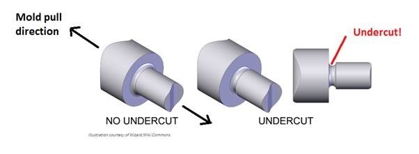
Illustration courtesy of Wizard/Wiki Commons
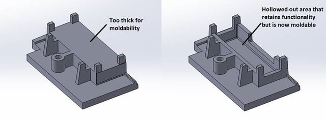
3. Are the wall thicknesses consistent? Are there very thick or very thin areas?
Thick areas were typically designed that way to make the part strong. But thickness dictates cooling time, which can lend itself to areas of sink. Instead, the engineer will determine which direction the maximum force will come from; which direction needs to be stronger. Then they’ll look to see if ribs can be used to reinforce the part. Depending on the part, thicknesses are generally run 3 to 5 mm. What you don’t want to do is go abruptly from a thick to a thin wall section. The part needs to have gradual transitions. If you have a thick section, you can shell — or hollow — it out.
Those are the three easy design issues engineers look for right away. From there they
might also look such things as draft angles. Simply, a draft angle is a slight taper of the sides/walls of the mold to decrease friction when you want to get the part out. Straight walls create friction. But the more draft angle you have, the easier it is to get the part out. Here’s my favorite draft angle illustration: a muffin pan. The sides of the muffin pan cups are slightly angled so muffin comes out easily.

Photo courtesy of Williams-Sonoma
There are plenty of other details a product engineer will look at, but those are the biggies. They’re simple things you can look over BEFORE you send your part/prototype/CAD drawings to the contract manufacturer. The process of product development can be time-consuming, but knowing simple fixes like these might just move things along a little more quickly.
To learn much more about injection molding do's and don'ts, click on our free download:


.jpg?width=176&height=56&name=MR_associatedNetwork_logo%20(1).jpg)