Design for Manufacturing (DFM) is the process of designing parts, components or products for ease of manufacturing with an end goal of making a better product at a lower cost. This is done by simplifying, optimizing and refining the product design. The acronym DFMA (Design for Manufacturing and Assembly) is sometimes used interchangeably with DFM.
Five principles are examined during a DFM. They are:
- Process
- Design
- Material
- Environment
- Compliance/Testiing
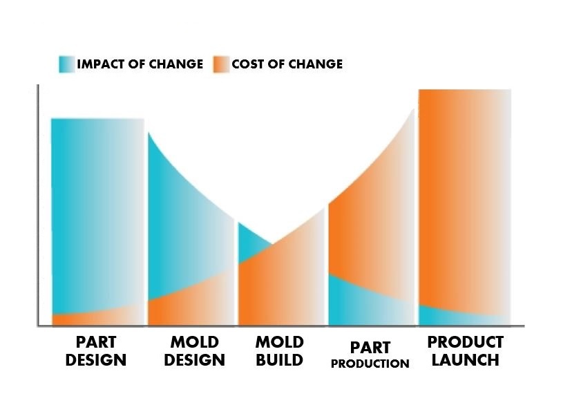
The following chart offers an excellent visual representation of the effect of an early DFM. As the design progresses through the product life cycle, changes become more expensive, as well as more difficult to implement. Early DFM allows design changes to be executed quickly, at the least expensive location.
Pulling stakeholders together early in the design process is easier if you're developing a new product, but even if you're dealing with an established product, challenging the original design is a necessary element of a thorough DFM. Too often, mistakes in a design are repeated by replicating a previous design. Question every aspect of your design.
- Look at the original drawings.
- Tear down the product.
- Look at competitive and near-neighbor products, as well as lead users such as medical and automotive.
- Talk to your contract manufacturer — who may have solved the problem with a different customer?
- Has someone else solved this problem a different way?
- Is there a way to make it better?
A lot of thought, time and effort go into a DFM. Jeff Tadin, our senior product development engineer, has almost 30 years of experience with product development, design and manufacturing. Today, he’s going to walk us through a hypothetical DFM process using a basic computer mouse (this mouse was not produced by East West Manufacturing.)

5 PRINCIPLES OF DFM: A CLOSER LOOK
1 | PROCESS
The manufacturing process chosen must be the correct one for the part or product. You wouldn't want to use highly-capitalized process like injection molding which involves building of tools and dies to make a low-volume part that could have been manufactured using a lower-capitalized method, such as thermoforming. That would be equivalent to using a tank to squash an anthill — a classic case of overkill. Let's see what Jeff has to say about selecting the right manufacturing process:
In determining the manufacturing process, Jeff said the DFM took into consideration the quantity of parts being made, the material being used, the complexity of the surfaces, the tolerances required and whether there were secondary processes required. You'll note that many of the same questions he asks with regard to process will also come up under the 'Design' heading.
2 | DESIGN
Design is essential. The actual drawing of the part or product has to conform to good manufacturing principles for the manufacturing process you’ve chosen. Here's Jeff, talking about design of the mouse:
In the case of plastic injection molding, for example, the following principles would apply:
- Constant wall thickness, which allows for consistent and quick part cooling
- Appropriate draft (1 - 2 degree is usually acceptable)
- Texture - need 1 degree for every 0.001” of texture depth on texture side walls
- Ribs = 60 percent of nominal wall, as a rule of thumb
- Simple transitions from thick to thin features
- Wall thickness not too small - this increases injection pressure
- No undercuts or features that require side action - all features “in line of pull/mold opening”
- Spec the loosest tolerances that allow a good product - and consult the trade organization for your manufacturing process on what is reasonable for that process
Be sure to discuss the design with your contract manufacturer, who can ensure that your design conforms to good manufacturing principles for the selected process.
3 | MATERIAL
It's important to select the correct material for your part/product. In this video, Jeff talks about some of the criteria that go into that decision:
Some material properties to consider during DFM include:
- Mechanical properties - How strong does the material need to be?
- Optical properties - Does the material to be reflective or transparent?
- Thermal properties - How heat resistant does it need to be?
- Color - What color does the part need to be?
- Electrical properties - Does the material need to act as a dielectric (act as an insulator rather than a conductor)?
- Flammability - How flame/burn resistant does the material need to be?
Again, be sure to discuss the material with your contract manufacturer, who might have access to existing materials in their portfolio which would allow you to secure lower material pricing.
4 | ENVIRONMENT
Your part/product must be designed to withstand the environment it will be subjected to. All the form in the world won’t matter if the part can’t function properly under its normal operating conditions:
5 | COMPLIANCE/TESTING
All products must comply with safety and quality standards. Sometimes these are industry standards, others are third-party standards and some are internal, company-specific standards.
Your manufacturer should have ISO-certified testing facilities. Find out: Who will provide UL, ETL and other third-party testing? Where will that testing take place?
FACTORS THAT AFFECT DFM
The goal of DFM is to reduce manufacturing costs without reducing performance. In addition to the principles of DFM, here are five factors that can affect design for manufacturing and design for assembly:
1 | Minimize Part Count
Reducing the number of parts in a product is the quickest way to reduce cost because you are reducing the amount of material required, the amount of engineering, production, labor, all the way down to shipping costs.
2 | Standaradize Parts and Materials
Personalization and customization are expensive and time-consuming. Using quality standardized parts can shorten time to production as such parts are typically available and you can be more certain of their consistency.
Material is based on the planned use of the product and it's function. Consider:
- How should it feel? Hard? Soft?
- Does it need to withstand pressure?
- Will your part or product need to conduct heat, electricity?
3 | Create Modular Assemblies
Using non-customized modules/modular assemblies in your design allows you to modify the product without losing its overall functionality. A simple example is a basic automobile that allows you to add in extras by putting in a modular upgrade.
4 | Design for Efficient Joining
Can the parts interlock or clip together? Look for ways to join parts without the use of screws, fasteners or adhesives. If you must use fasteners, here are a few tips:
- Keep the number, size and variation of fasteners to a minimum
- Use standard fasteners as much as possible.
- Use self-tapping and chamfered screws for better placement.
- Stay away from screws that are too long or too short, separate washers, tapped holes, round heads and flatheads.
5 | Minimize Reorientation of Parts During Assembly & Machining
Parts should be designed so that a minimum of manual interaction is necessary during production and assembly.
6 | Streamline Number of Manufacturing Operations/Processes
The more complex the process of making your product, is the more variables for error are introduced. Remember what Jeff said: All processes have limitations and capabilities. Only include those operations that are essential to the function of the design.
7 | Define "Acceptable" Surface Finishes
Unless it must be trade show grade, go with function rather than flashy for your surface finish.
BONUS: 4 KEY QUESTIONS ABOUT PLASTIC INJECTION MOLDING & DFM
Jeff talked a good bit about plastic injection molding in the videos. Here are four important questions to keep in mind about DFM and the injection molding process:
Which direction will the tool pull?
Here’s how it works: A tool (or mold) is made of two halves. The hot plastic liquid is poured into the mold, then quickly cooled. The two halves are pulled apart and there’s your part. If any feature in your part moves in a direction other than the pull of the mold, that will complicate the tooling and the tool will cost more.
Are there undercuts or features that will get trapped?
Undercuts are protrusions or recesses in the design that prevent the mold from sliding away from the part. They can get caught in the tool and cause damage. If the design element causing the undercut is absolutely necessary it’s possible to get around it by using a slide, but that increases the price of the tool. Better to get rid of the undercut by changing the design.
How consistent are the wall thicknesses?
The thick areas on plastic parts are designed that way for strength. But thickness also dictates how long it takes for the part to cool, and the longer it takes to cool the greater the chance for sink. Sink is not good. It is an area of weakness in the part. Also, longer cycle times increase part cost, as the amount of press time to mold the part is increased.
To address this problem, an engineer will thin a thick area out and reinforce it with ribs. Thin walls are not good either, however. Walls that are too thin can easily break. Depending on the part, wall thicknesses will run from 3 mm to 5 mm in thickness. Engineers will also look for transitions between thin and thick walls, making sure the transition is gradual.
Does the design need draft angles?
Straight sides or walls cause the part to stick to the mold, making the parts difficult to remove from the tool. Draft angles are slight tapers of the walls or sides of the mold which assist in the part ejecting properly from the mold. The greater the draft angle, the easier it is to get the part out.
10 OUTCOMES OF AN EFFECTIVE DFM
The book Computer-Aided Manufacturing offers 10 generally accepted Design for Manufacturing principles that were developed to help designers decrease the cost of and complexity of manufacturing a product. The results of a successful DFM are quantifiable in a host of ways.
- Minimize the number of product parts. Limiting the number of parts in your product is an easy way to lower the cost of a product. Why? Because it automatically reduces the amount of material and assembly labor required. Reducing the number of parts also means less engineering, production, labor and shipping costs.
- Use standardized parts wherever possible. Customization is not only expensive, it’s time consuming. Standardized parts are already made to meet the same quality metrics, every time. They are already tooled. So you save costs and you won’t have to wonder whether they’ll pass inspection.
- Create a modular design. Using modules can simplify any future product redesign, and also allows for use of standard components and the re-use of modules in other projects.
- Design multi-functional parts. This seems rather obvious, but it’s a simple way to reduce the total number of parts: design parts with more than one function.
- Design multi-use products. Building on the point above, different products can share parts that have been designed for multi-use. Can your product use standardized parts that can are used in multiple products?
- Design for ease of fabrication. Choose the ideal combination between the material and manufacturing process that will minimize production costs. Ridiculously tight tolerances are a no-no. [More about that below.] Avoid expensive and labor extensive final operations as painting, polishing and finish machining.
- Design your product to join without using screws, fasteners or adhesives. Is it possible for your product to interlock or clip together? Screws add only about 5% to the material cost, but 75% to the assembly labor. Remember: if fasteners are required, try to keep the size, number and type to a minimum and use standard fasteners whenever possible.
- Design your part to minimize handling, especially during production and assembly. Handling includes positioning, orienting and fastening the part into place. For orientation purposes, use symmetrical parts wherever possible.
- Minimize assembly direction. If possible, your parts should assemble from one direction. Ideally, parts should be added from above, parallel to the gravitational direction (AKA downward.) This way assembly is facilitated by gravity rather than fought by it.
- Design your part to maximize compliance. Rely on built-in design features like tapers or chamfers, or moderate radius sizes to guide insertion of equipment and to protect the part from damage.
It’s been said that about 70 percent of manufacturing costs of a product — the cost of materials, processing and assembly — are determined by design decisions. If that’s the case, then you want to make sure you are adhering to the best design practices possible.
THE DANGER OF TIGHT TOLERANCES IN DFM
Any engineer worth their salt is going to also take a very close look at the tolerances specified in the part’s drawings. Tolerance is the total amount a specific dimension is allowed to vary, and manufacturers often receive drawings from customers with unreasonably tight tolerances that can wreak havoc on an RFQ.
- Lower cost for tooling
- Ease of manufacturing
- Fewer defects
- Greater yields
The chart below shows the drop in yield and the rise in cost as the tolerance increases.
The bell curve shows measurements on a particular dimension, including the Upper Spec Limit (USL) and Lower Spec Limit (LSL), which is based on the tolerances. The tighter the tolerance, the narrower the bell curve has to be for the dimensions to be in spec.

All manufacturing processes have limits on what is reasonable to manufacture — that's the gap between USL and LSL. Consult with your contract manufacturer or the trade organization for the process, if you are unsure. There is a lot of data on most common processes to give you guidance on what is reasonable to specify.
Tolerances should be driven by three things:
- the manufacturing process;
- the material used;
- the sensitivity of the features to variations.
Managing tolerances is an essential part of a good DFM, and there should always be a justification for the numbers on the drawing.
HOW LONG WILL THE DFM TAKE?
You might be wondering what kind time you'll have to invest in the DFM? That really depends on the quality of the design that you start with.
One of our engineers likened it to proofreading an essay. For example, if you understand the writer's intent, it's much easier to make the corrections in the text. But if you're reading the essay without a clear understanding of intent, you might go back and forth with corrections before you come up with a finished copy.
The DFM is similar. Perhaps the design is clean, answering all questions for all parties. You'll be ready to go in a day or two. But depending on the number of questions, their difficulty, and the speed and thoroughness of the answers, you might be waiting a week or more. Take a deep breath. Your contract manufacturer will be able to give you a better idea of how long they think it will take. Remember speed isn't the goal: a quality product is.
A good DFM hopefully concludes by reducing the complexity of the design and satisfying the customer's requirements for price, specification, material and scheduling.
In other words, the design is deemed manufacturable and ready for the next step on the road to production.
But that's another blog post for another day
Are you ready to learn more about what to look for in a DFM partner? Click on the download below:


.jpg?width=176&height=56&name=MR_associatedNetwork_logo%20(1).jpg)