So you've designed a product. You've gone through the RFQ process, sharing your CAD drawings with engineers who probably made even more tweaks. The part is going to be made of plastic using the injection molding process. But you've never made a plastic injected part before. There are a lot of new words and phrases being tossed around and you don't really know what they all mean.
Runner Sprue? Water Baffle? Ejector Pin?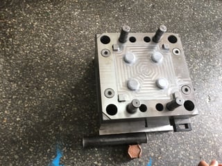
Is a tool the same thing as a mold? Why is mold spelled two ways (mold vs. mould)?
And how does the whole thing actually work?
No one would blame you for looking for a glossary of terms right about now. Fear not. Below, we break down the components of an injection mold in simple, easy-to-understand language. It even includes labeled cutaway drawings. I promise, if you didn't understand how an injection mold worked before, you will after reading this.
COMPONENTS OF AN INJECTION MOLD
An injection mold is a tool comprised of a series of parts that allows molten plastic to be formed and cooled in such a way as to create a discrete part shape.
DETAILED COMPONENTS
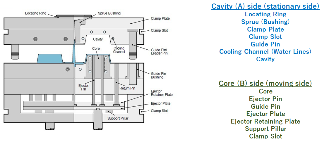
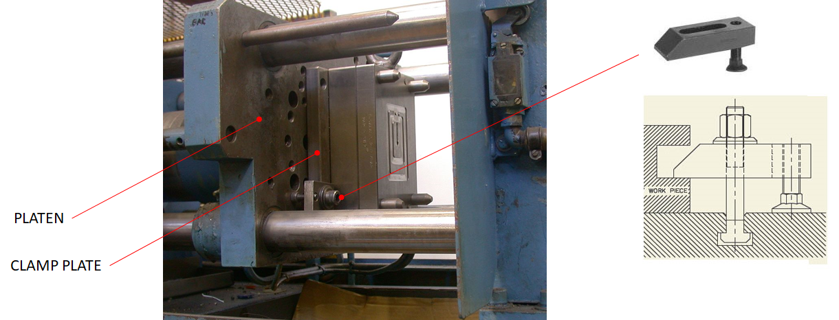
CLAMP PLATES
Mold halves are attached to the molding platens by the clamp plates. Mold clamps use large bolts to hold them in place; other machines hold the mold onto the platen with magnets.
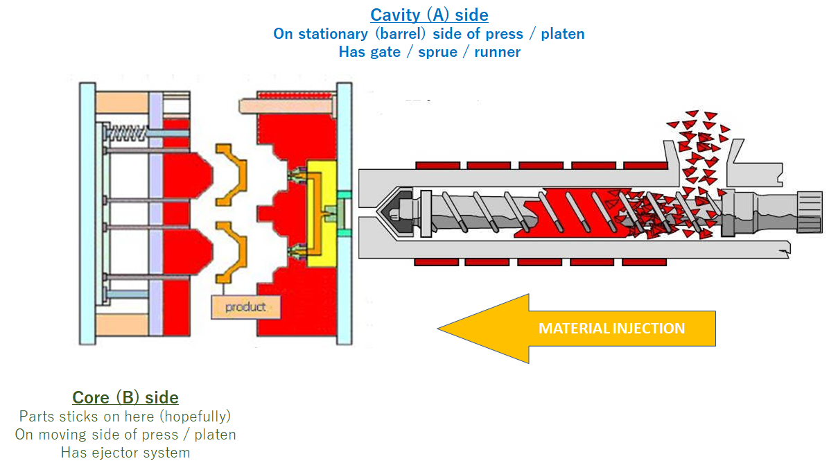
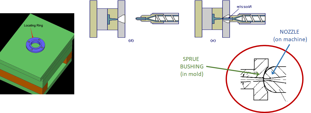
NOZZLE/SPRUE BUSHING
Liquified plastic is pushed through the nozzle of the barrel of the molding machine. The nozzle seats against a surface on the mold called the sprue bushing and locating ring, which help center the nozzle to the mold.
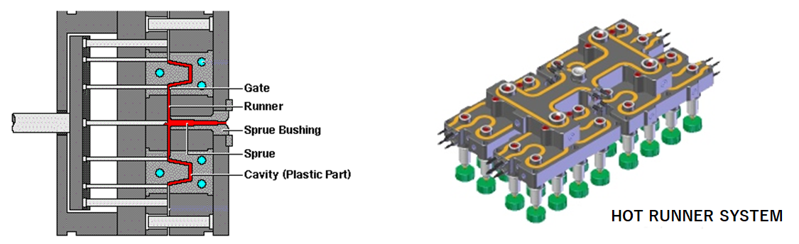
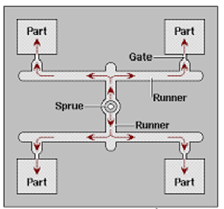
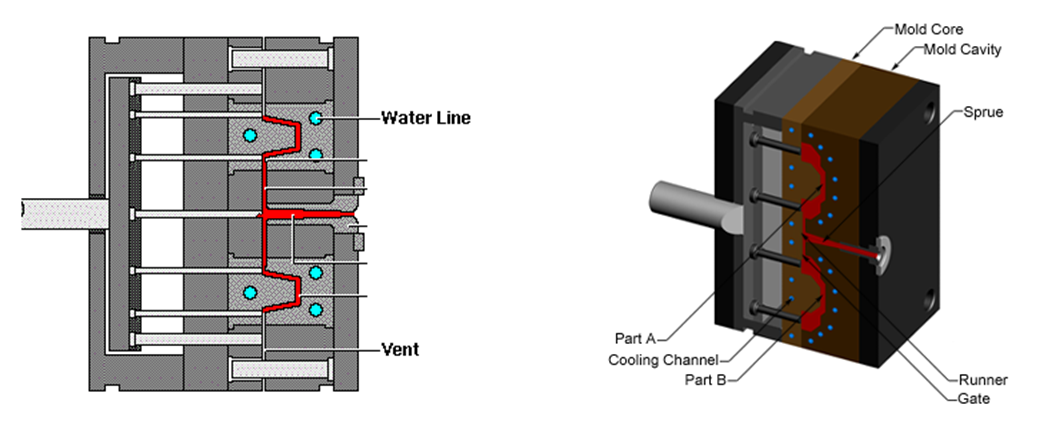
FEED SYSTEM
Plastic flows through the sprue bushing in a sprue, then to individual runners which take the material to the gates - the entry point of the material to the individual cavities.
The sprue and runners can be reground (chopped up) and reused. They can be eliminated by using a hot runner system.
CAVITIES
Cavities are areas of the mold where the part is formed into desired shape. Molds must be balanced, so there are typically only a certain number of cavitations allowed (1,2,4,8, etc...)
COOLING SYSTEM
Plastic is injected hot and is cooled by cooling channels that allow conduction to cool the part. Working fluid is typically water, although oil can be used in high temp applications.
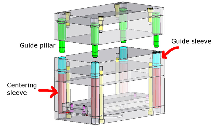
GUIDE PILLARS/BUSHINGS
Cavity and core mold halves are insured to be in proper alignment during mold close by the use of guide pins (or pillars) and guide bushings (or sleeves).
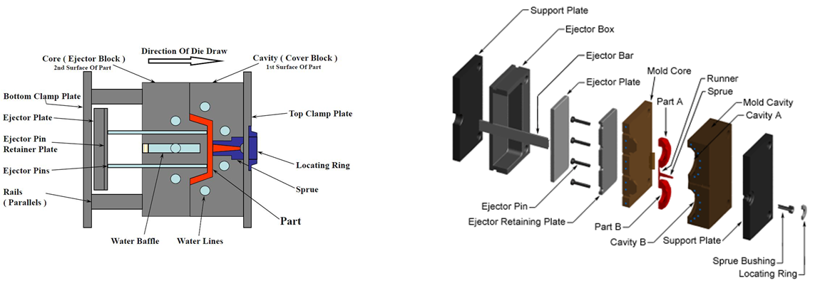
EJECTOR SYSTEM
Parts are pushed off of the core using a series of pins or bars. These series are called the Ejector System.
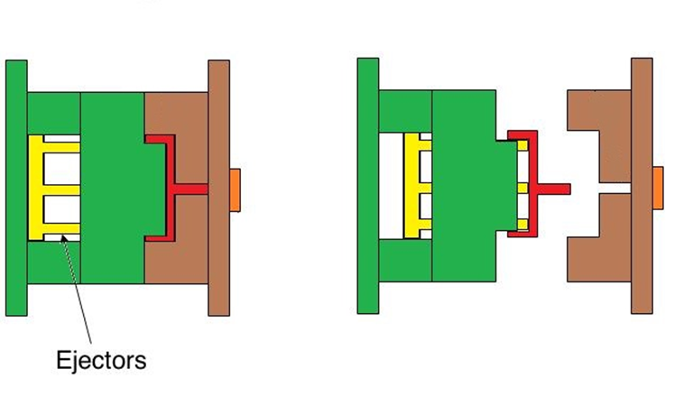
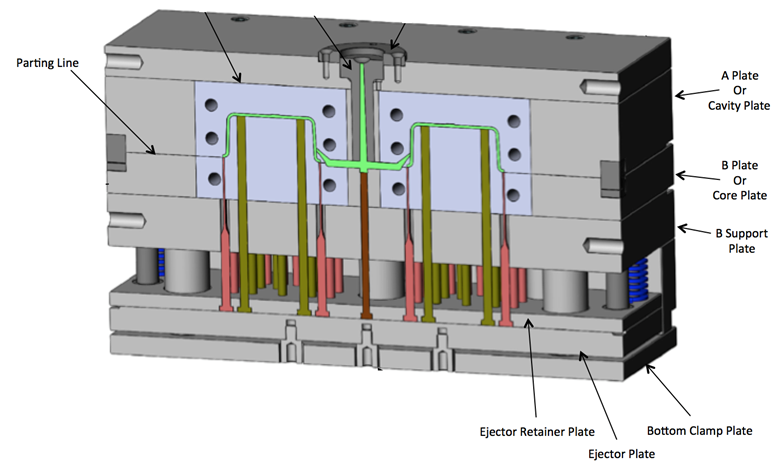
EJECTOR PLATE SYSTEM
The ejector pins are mounted in an ejector plate. The motion of the ejector plate forward allows the pins to move forward, pushing the part off the core. The ejector retaining plate holds the pins into the ejector plate.
If you're up for an even deeper dive in the world of plastic injection molding, check out this video from a previous blog post. In it, one of our capable engineers explains the ins and outs of injection molding. The video is about 12 minutes long, and packed with great information.
Read more:
- How to Get Your Plastic Injection Part Design Ready for Manufacturing
- Mold Flow Analysis Can Save Your Plastic Injection Mold Design
Liked Jeff's presentation? Click the download for a free copy of his slides:


.jpg?width=176&height=56&name=MR_associatedNetwork_logo%20(1).jpg)